
John R. Bentley 2011.
Boring the
Main Bearings
- for the Stuart Compound Launch Engine -
- what a lovely name!
This is the first work of 2011 on the engine after I put the project aside for a trip to Britain and Ireland beginning in April of 2010. When I returned I found plenty of things to do during the summer and autumn (the weather was unusually pleasant) and consequently I only returned to the project in January of 2011.
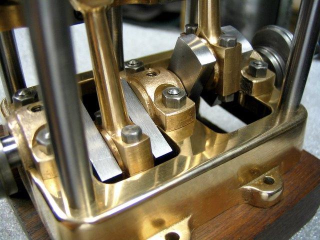
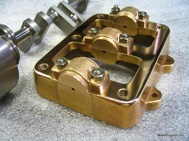
This was the state of the soleplate and bearing caps at that time


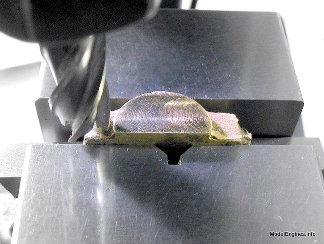
The first step was to mill the sides of the caps parallel
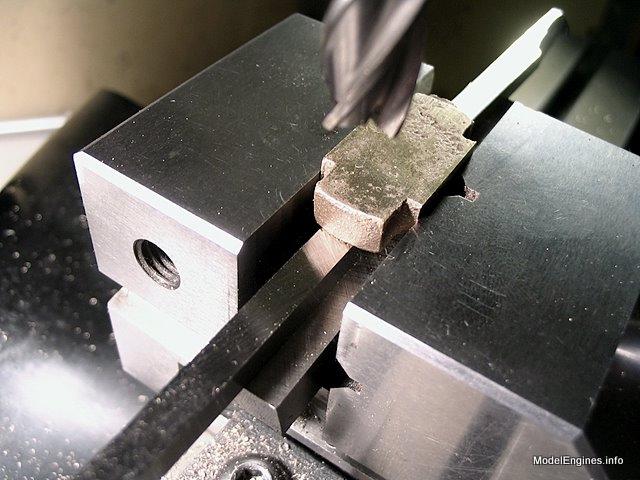
The milling described above allows holding the caps in the vise
so that the bottoms can be milled at 90 degrees to the sides
Marking out

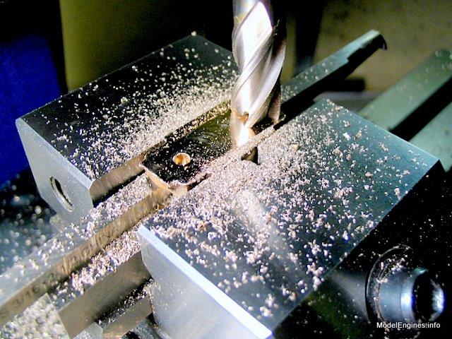
Drilling the fastening holes

A test fit

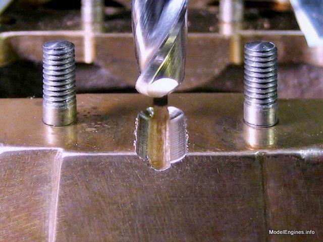
Spotfacing for the nuts

Using lathe bits for packing underneath to ensure the bottom is milled parallel to the two spotfaced surfaces
A quick test to check after the caps are milled to final height
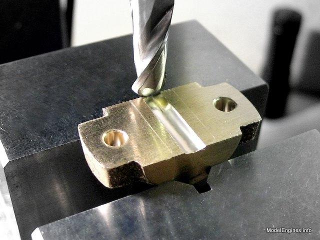
Beginning the main bearing groove with the first pass of a 1/4" ball endmill
Using the same endmill to make the matching grooves in the caps
Just a rough check (while the bore is still undersize) to make sure nothing is obviously off
(the final diameter will be 5/16")

A piece of 5/16" silver steel

( in North America the nearest equivalent to this metal is called "precision-ground water-hardening drill rod" )
Here I have tapered the silver steel from 5/16" to 1/4" at one end and ground a flat so it forms a special reamer
(the lower piece is a 1/4" pilot which screws in the end of the reamer)

Testing the assembled reamer before hardening
The 1/4" pilot section guides the larger reamer section by utilizing the other two bearing holes
The reamer was designed to guarantee the alignment of the three bearings in this manner:
Note the original 1/4" holes were lined up correctly as an accurate guide groove was first cut in the soleplate using milling machine.
The reamer section after initial hardening
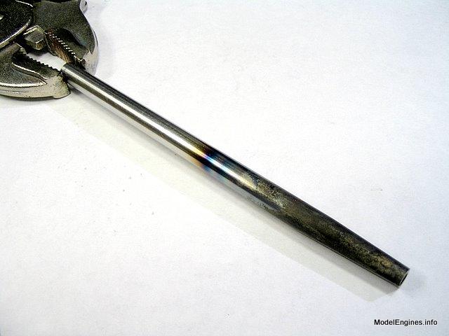
After this photo was taken the reamer was cleaned and tempered to a light straw colour
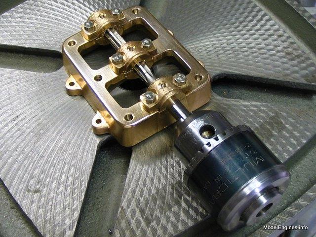
The new reamer in use, being powered by a 40-year old Black &Decker hand drill

To ease the strain on the drill (and the old guy holding it) I left the bearing caps raised somewhat at first
There is a full 1/32" of metal to be cut away from around the bore...
For extra help I also used the tapered end of a standard 5/16" straight reamer to start each hole, turning it by hand in the chuck
Approaching final size, I put paper strips under the caps to avoid
making the bore too large to precisely fit around the crankshaft

The inner entrance to each hole will need to have a radius cut to provide clearance for the crankshaft.

I started with a countersink and rounded the resulting chamfers with a fine half-round file

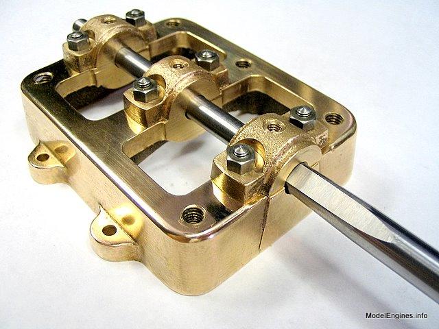
Bedding in the new bearings under power from the Taig lathe
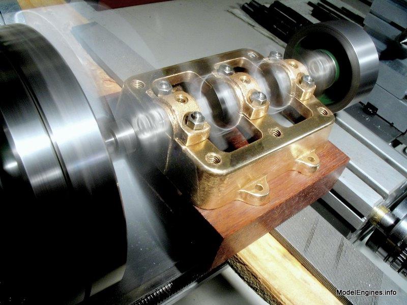
Although this looks fast, the effect is caused by a slow camera shutter
- actually I used a varying range of speeds - most of them below 800 rpm
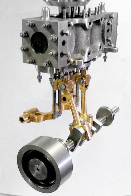
The mating of the "two great halves" of this engine is looming ever closer
...but I will save that for another page...
Back to
Compound Launch main page
or
Castings, Materials and Fastenings
Soleplate
Cylinder Block
Top Covers
Bottom Cylinder Covers
Steam Chests
Crosshead Guides and Bracket
Crankshaft
Eccentrics
Flywheel
Connecting Rods and Crossheads
Main Bearings (this page)
Pistons
Fittings: Oil Cups
Fittings: Drain Cocks
Fittings: Exchange Pipe, Flanges and Glands
Stephenson Link Reversing Gear (5 pages)
Completing and Erecting the Compound Launch Engine
or
Return to main website home page
ModelEngines.info
![]()
(c) John R. Bentley 2011.