
John R. Bentley 2010.
Machining the
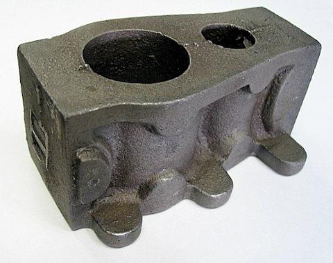
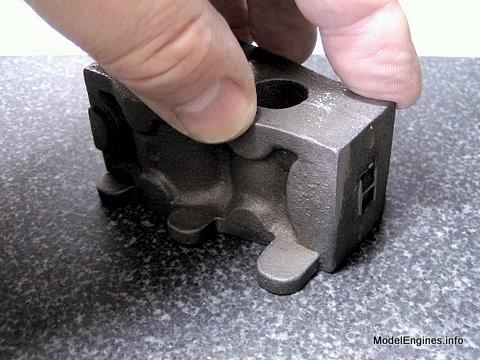
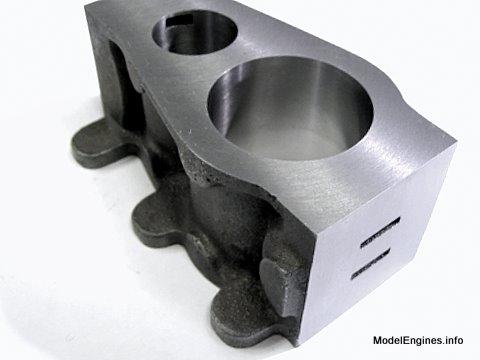
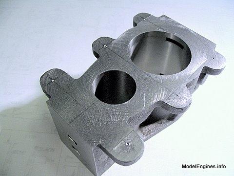
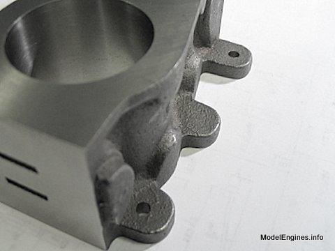
The raw casting: some irreversible decisions will need to be made at this stage
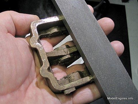
I used a large flat file remove some bits of unnecessary metal on the top and bottom of the block.
I suppose this only needs to be done on the bottom, but I wanted to make a few quick measurements to be certain the casting was reasonably symetrical and included enough metal in the required places to support the machining operations which are to follow.
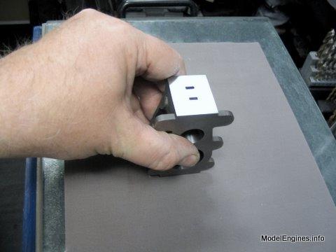
When only removing high spots in preparation for milling, I get the best results by holding the unit in my hand as shown. Otherwise filling and or sanding flat surfaces is best done with the file or cloth on a firm flat surface and drawing the casting along toward you in that direction only. I avoid clamping the casting securely when filing as it can quickly lead to rounding the overall surface.
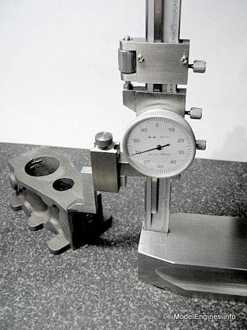
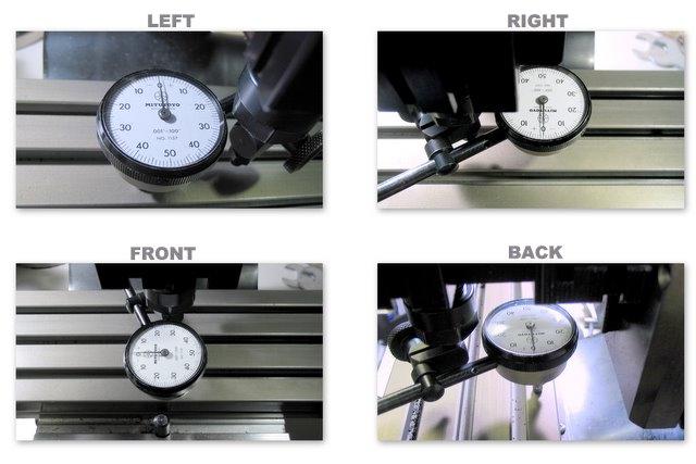
That done - now to make a few measurements to see that the top and bottom are close to parallel and sit without leaning to one end and/or one side. If it did, this could be corrected at this point, but would end in disaster if left unchecked.
I didn't really expect any problem with Stuart castings in this respect - the set for this engine has been produced for many years. Any dimensional errors would long ago have been discovered and corrected.
Ensuring that the mill column is perpendicular to the table ("tramming")
This is essential for too many reasons to tell here. Not only does bad alignment result in stepped surfaces, but cylinders that aren't perpendicular with the base will cause binding in the crosshead guides and in the crankshaft....and a thousand other things.
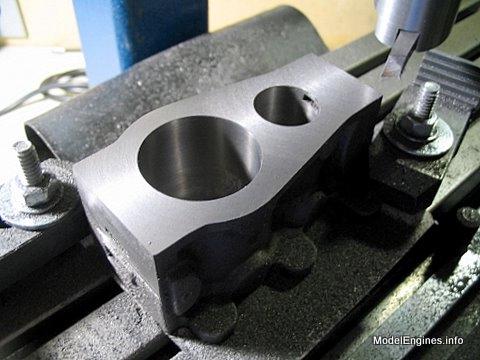
Taking a light skim off the top surface (not yet to size)
This is to produce a level and steady surface to allow creating the main reference surface on the bottom of the casting as shown below.
I used the Taig (Peatol) micro mill for this, but it is equally easy to accomplish on the lathe by holding the casting in a 4-jaw chuck or clamped to a faceplate.
Again, this is a natural for a small lathe - I once constructed the nearly identical Stuart Twin Launch engine completely using only a Taig lathe and an electric hand drill.
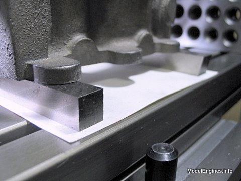
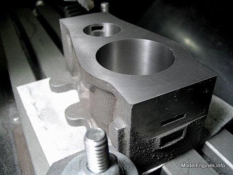
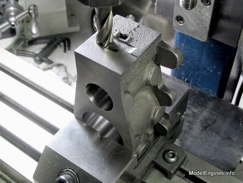
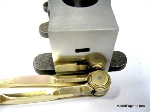
The casting is raised on two lathe tool blanks to allow the cutter to pass
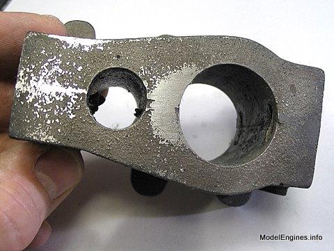
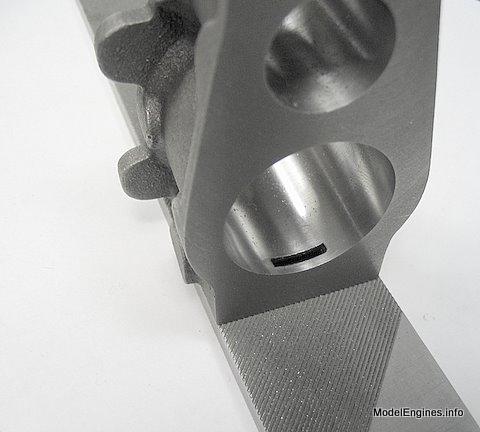
On this end obviously the steam passages were twisted when cast. This should be a realatively easy matter to correct by straightening the ports with a tiny end mill. The larger central exhaust port has yet to be milled in.
Cylinder Block Casting
- for the Stuart Compound Launch Engine -
But first some preparation is needed before locating a starting point
This shot of the soleplate is from the previous page, but it shows the file in action
The aim is to get the castings to sit level without rocking by doing the minimum amount of filing.
These castings tend to be close to final size, so it is very important to constantly measure surfaces that are being milled and keep a clear mind in order to prevent "taking it all off one end"! Initially some light milling is needed so more accurate measuring and marking out can be done.
But first things first:
This only needs to be done reasonably and responsibly, it shouldn't be made into a life's work. Vibration, tool asymetry and other factors will overshadow excessive efforts in tramming down to the molecular level! Still - there is nothing wrong with our doing best.
I felt that it would be wise to bore and finish the cylinders prior to bringing the top and bottom surfaces down to size. There is often a slight widening of the bores at the extremities created during honing and/or lapping. Milling down the block after these operations will cut away these areas.
Notice a faint red centre line on the block in the photos below. It was scribed very lightly and I used a red grease pencil to fill the line well enough for me to see. I later marked it more clearly with a pencil for future setups.
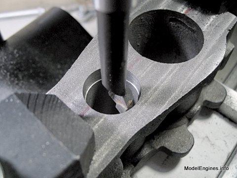
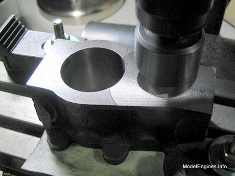
Here the modified Sherline boring head is clearly visible on the Taig mill
completely through the hole without boring through the mill table
Boring the high pressure (H.P.) cylinder
Boring the low pressure (L.P.) cylinder

Bringing the H.P. cylinder to size with an adjustable reamer
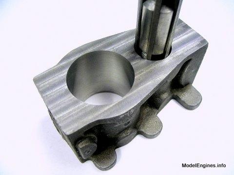
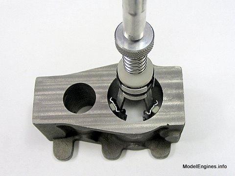
A 3-stone honing tool

The honing tool at work in the L.P. cylinder
Drawing a centreline
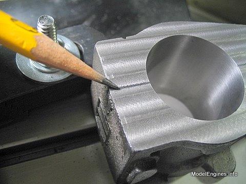
Setting the centerline parallel with the X-axis
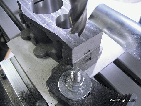
Taking a pass with an endmill across the L.P. valve face for reference
The H.P. valve face partly machined

Note the cast-in port is skewed (more about that later)
Another view
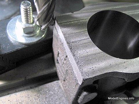
Here the spinning flycutter is milling the top surface of the block
Still a bit more to go
Now it is time to complete the port faces
A view of the L.P. face before final finishing
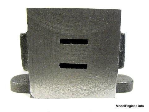
H.P. valve face

The steam passages are rectangular channels which follow an S-curve inside the block to exit into the cylinder. Where they break the surface on the valve face, the resulting holes form the valve ports.
Draw-filing the port face
Partially finished - many of the high spots are already flattened in this view
More improvement

Although reflective it is not a perfect mirror finish - this will allow mating the valve with this surface
(during the engine break-in period)
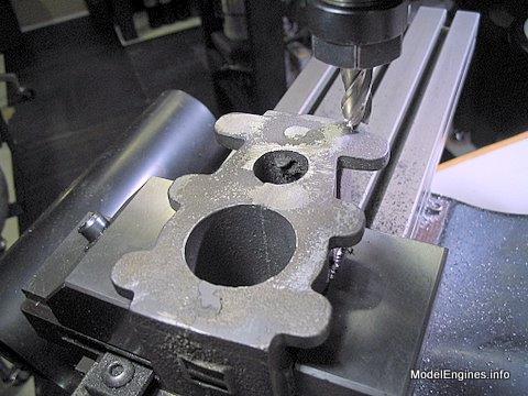
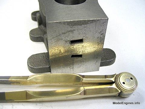
Now it is time to straighten those ports somewhat with a 1/16" endmill
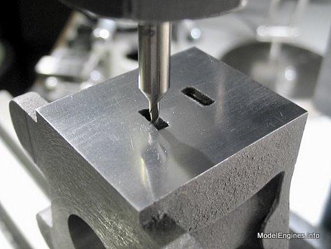
There is very little extra port size allowable
- so only bare minimum enlargement is acceptable
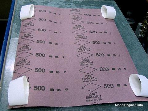
Ready to tape some 500-grit abrasive cloth to a glass surface plate
Some careful hand finishing on the L.P. port face
"Smooth as a baby's...um...arm!"
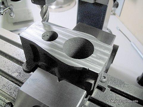
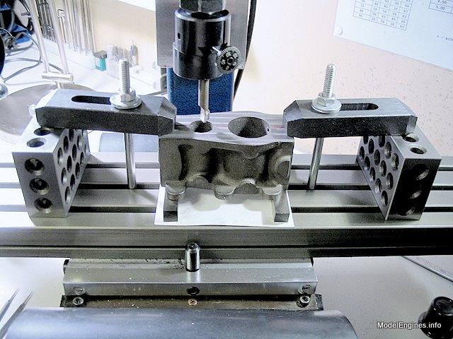
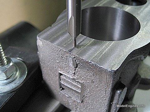
Marking out for the supporting column holes
This surface will be milled down to the correct depth later
(also the lugs will be reduced in size as shown on the plan)
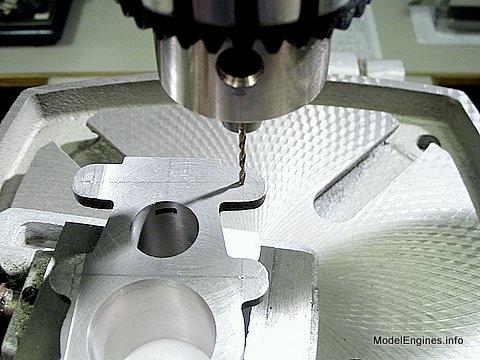
Lots of complicated-looking operations are actually easy - here the opposite is true
- marking and drilling these holes in the correct relationship to the casting is very difficult
The three lugs on the back - drilled to size to clear the 4BA threaded column ends
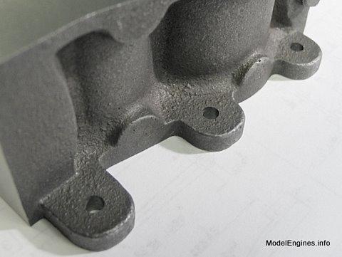
There are only two columns on the front - the spare lug will be machined away
(it is included for those wishing to make a left hand engine for twin-engine boats)
It took me a full day to place these five holes

Back to
Compound Launch main page
or
Castings, Materials and Fastenings
Soleplate
Cylinder Block (this page)
Top Covers
Bottom Cylinder Covers
Steam Chests
Crosshead Guides and Bracket
Crankshaft
Eccentrics
Flywheel
Connecting Rods and Crossheads
Main Bearings
Pistons
Fittings: Oil Cups
Fittings: Drain Cocks
Fittings: Exchange Pipe, Flanges and Glands
Stephenson Link Reversing Gear (5 pages)
Completing and Erecting the Compound Launch Engine
or
Return to main website home page
ModelEngines.info
![]()
(c) John R. Bentley 2010.