
John R. Bentley 2010.
Machining the
Unlike the top covers, the lower cylinder covers on this engine are key components in the drive train from the pistons to the crankshaft. They support the upper ends of the crosshead guides and consequently define the location of the supporting bracket for the guides on the engine's columns - a component which also locates the reversing shaft.
This job went very well - you can see that two photos down. However at a later point in construction I managed to get into a considerable amount of unnecessary trouble as a result of following the plans too closely regarding the depth of these threads. If you want to read more Click Here
Lower Cylinder Covers
- for the Stuart Compound Launch Engine -
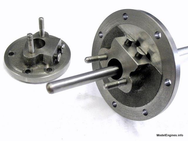

These covers determine the degree of parallelism between the crosshead travel and the piston rod travel. Of course in addition they contain the packing glands for the piston rods. The lower covers are not at all difficult to machine, but the builder should adhere closely to the stated dimensions on the plans. (I do take exception to the suggested depth of the crosshead slider mounting screws however and I have made more comment about that later on this page)
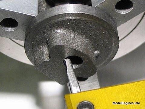
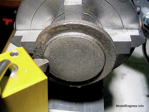
Here is a bottom view of the castings showing the stuffing boxes


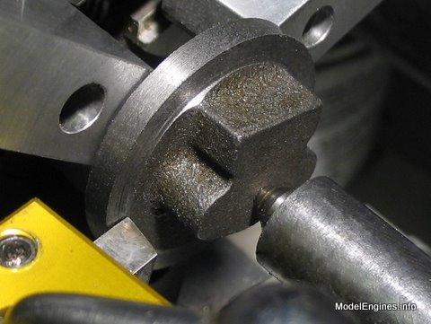


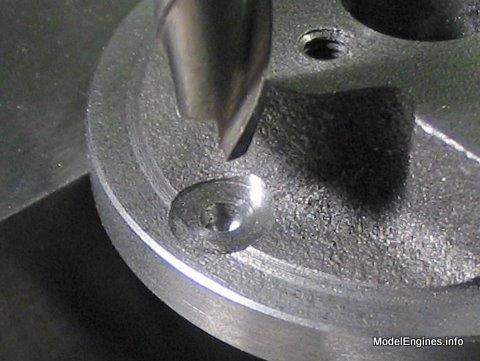
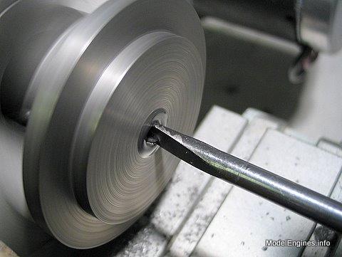
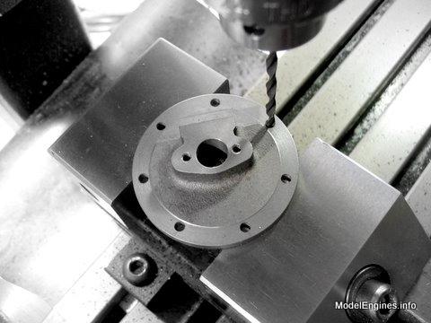
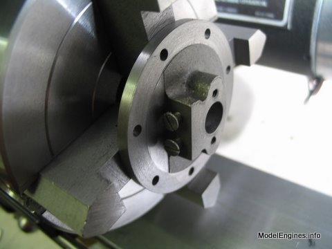
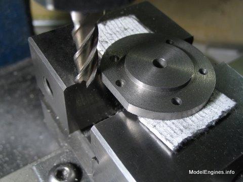
Above and Below: spotfacing for the mounting nuts


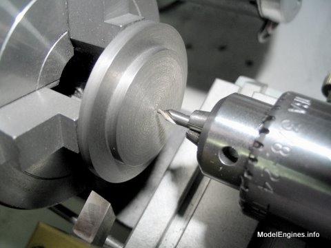
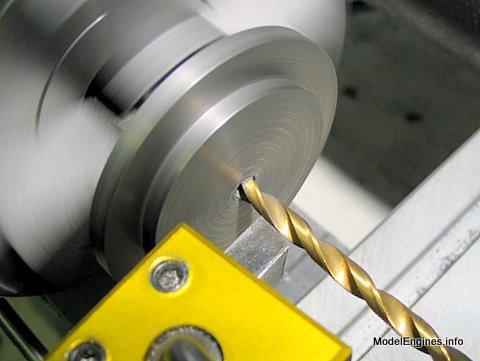


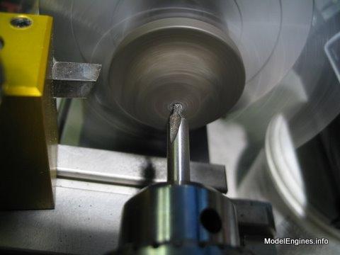
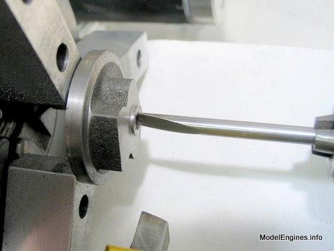
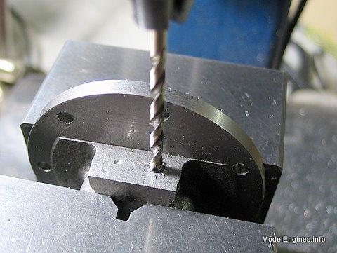
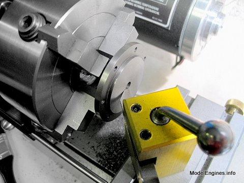
Taking a reference position from the bottom edge of the cover with the point of a 1/8" centre drill

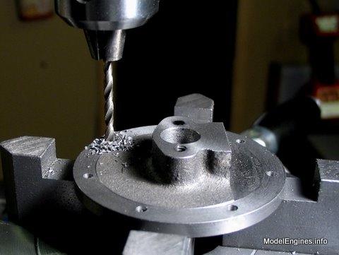
Drilling the holes for the crosshead guide attachment screws
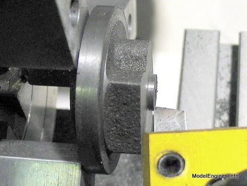
Spotfacing for the stud nuts on the H.P. cover

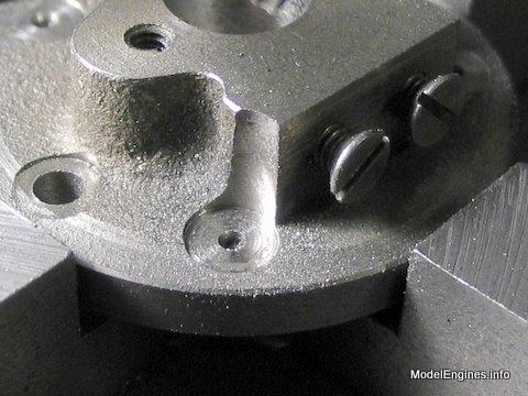
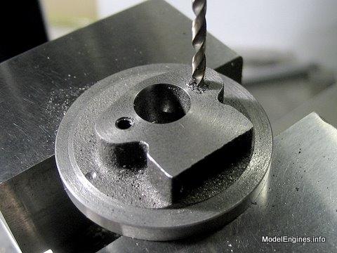
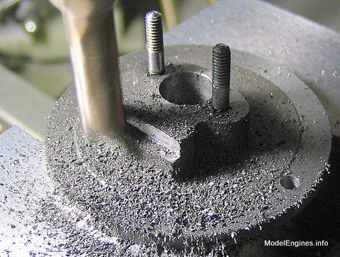
Spotfacing this hole and its counterpart left a rather unusual shape...
So I shaved off a bit of metal with the endmill so it would look better.

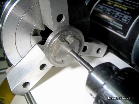
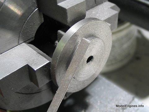
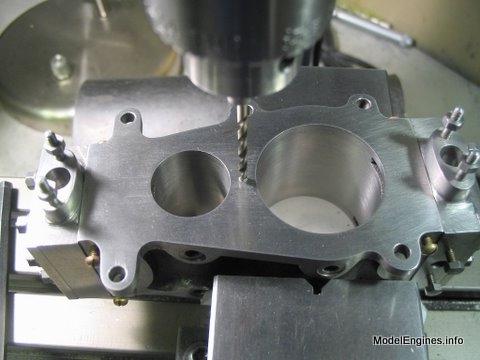
Now to the big cover -
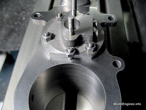
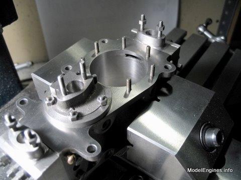
Perhaps the most important stud hole - drilled on the centerline halfway between the two cylinder walls

Marking the H.P. cylinder stud holes in the block using the cover as a guide

Note that a clearance drill was used - but only to mark the holes
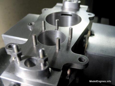
The marks ready to be drilled and tapped for the studs
No - those studs are not leaning outward
(it's the camera lens causing "diverging verticals")
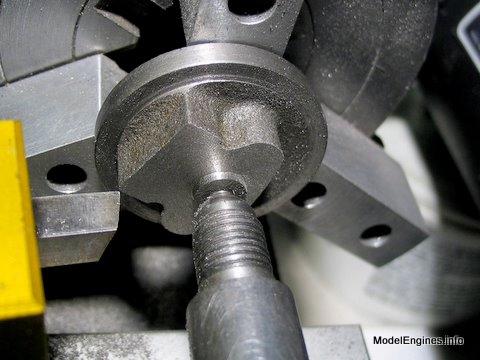
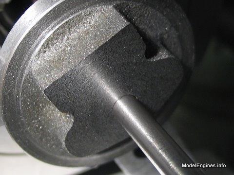
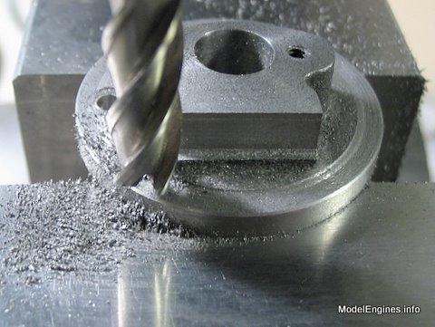
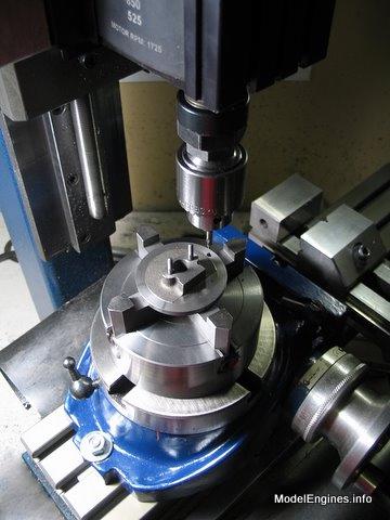
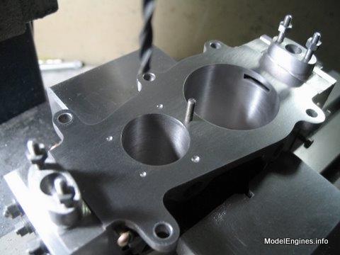
Begining the milling of the "flat spot" which will bisect one mounting hole
(where both covers share a single stud)
Same drill as before
No pun intended :-)
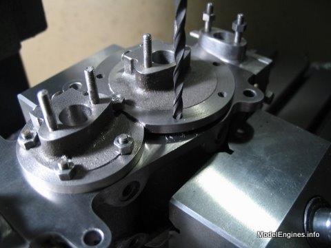
(marking the L.P. lower stud holes)
Ready for drilling and tapping

Compound Launch main page
or
Castings, Materials and Fastenings
Soleplate
Cylinder Block
Top Cylinder Covers
Lower Cylinder Covers (this page)
Steam Chests
Crosshead Guides and Bracket
Crankshaft
Eccentrics
Flywheel
Connecting Rods and Crossheads
Main Bearings
Pistons
Fittings: Oil Cups
Fittings: Drain Cocks
Fittings: Exchange Pipe, Flanges and Glands
Stephenson Link Reversing Gear (5 pages)
Completing and Erecting the Compound Launch Engine
or
Return to main website home page
ModelEngines.info
![]()
(c) John R. Bentley 2010.