
John R. Bentley 2011.
Machining the
The pistons were turned from cast iron and made to the same diameter as the cylinder bore. Unlike aluminum pistons, the thermal expansion rate is identical to that of the cylinder walls. The combination of cast iron against cast iron forms one of the best known sliding bearing surfaces among common materials. The low pressure piston is 1 1/4" diameter and the high pressure piston is 3/4" diameter. Each piston carries two identical cast iron rings which are located 1/32" apart.
Low Pressure and High Pressure Pistons
- for the Stuart Compound Launch Engine -
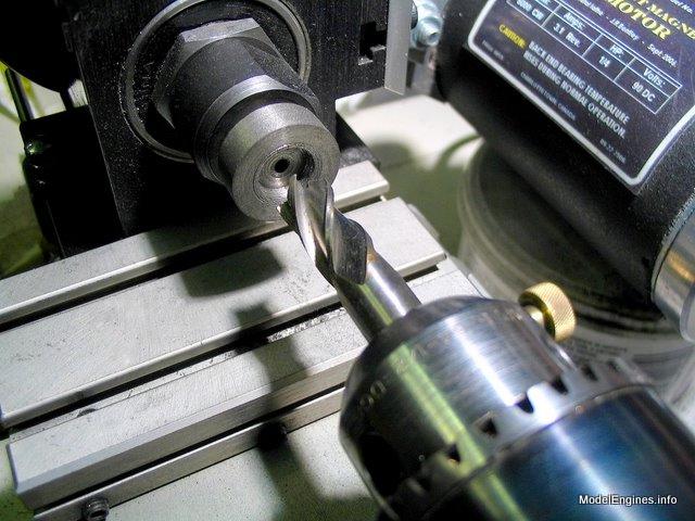
I center-drilled one end of each rod to enable tailstock support while turning the pistons

The two finished pistons waiting to be surrounded by cylinders
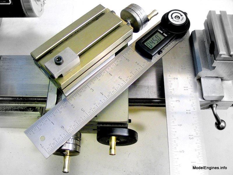
First the rods were threaded 5BA on both ends

Here the two piston rods are temporarily in position

The raw casting for the LP piston

Initial turning shows some pitting in the cast surface
This is not uncommon in this type of sand casting

Setting the Taig compound to 45 degrees to finish the piston's bumps and recesses
Tapping the casting 5BA to match the piston rod
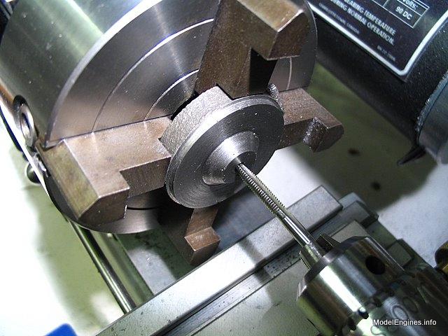
I have flipped the casting around in order to face turn the bottom

Now the piston is screwed on to the rod and held in a collet
so that it can be finish-turned concentrically to the rod

Cutting the 1/16" grooves for the rings
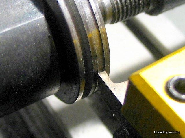
Note that the tool chosen is slightly narrower than the finished groove (left)
- it is always a good practice
The completed piston (not yet fully screwed into the crosshead)

These are Stuart rings - still black from heat treatment
Their edges will become polished when they are seated in the cylinders
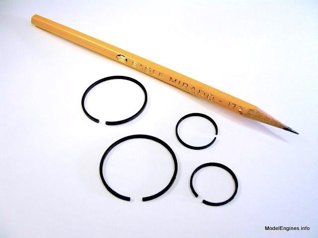
I very gently worked the rings over the piston with my fingers and into the grooves
Since I only have three hands I don't have any pictures of the actual process
- but really, there was nothing to it.

To give you a break I have included the pictures of the HP piston below almost without comment
- it's just the same only different!


After this recess was made, the sides were tapered to 45 degrees as in the LP piston

The two finished pistons awaiting installation
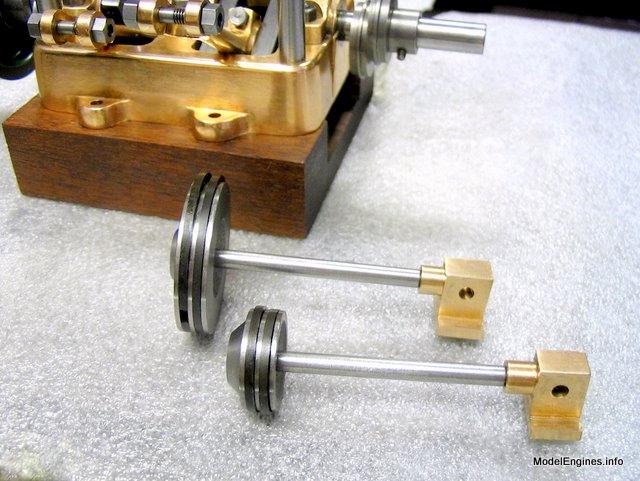
Ready for the mounting of the cylinder block

Obviously that is more than perspective distortion...
- the the two bottom cylinder covers were leaning apart in this temporary setup.
The straight edges of the covers are supposed to be touching.
Yep! The pistons fit the big holes!

Back to
Compound Launch main page
or
Castings, Materials and Fastenings
Soleplate
Cylinder Block
Top Covers
Bottom Cylinder Covers
Steam Chests
Crosshead Guides and Bracket
Crankshaft
Eccentrics
Flywheel
Connecting Rods and Crossheads
Main Bearings
Pistons (this page)
Fittings: Oil Cups
Fittings: Drain Cocks
Fittings: Exchange Pipe, Flanges and Glands
Stephenson Link Reversing Gear (5 pages)
Completing and Erecting the Compound Launch Engine
or
Return to main website home page
ModelEngines.info
![]()
(c) John R. Bentley 2011.