
John R. Bentley 2010.
Machining the
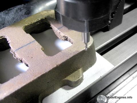
I started out by drilling undersize holes, in case any small corrections were needed.
One hole was slightly off, so I used a small endmill to change the location of the entry - then drilled it out to size, leaving it correctly positioned and showing no evidence of my error.
The Unified threads are quite like Metric threads - a 60° V-thread form. However their BA counterparts are at 47.5° and are quite rounded at the crests and roots.
BEARINGS:
Much more work was done on the engine in 2010, but the bearing job was left for another year - until Jan 2011.
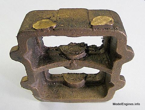
Soleplate Casting
- for the Stuart Compound Launch Engine -
(that doesn't make it easy to machine - even for razor sharp endmills)

The bed is cast from Gunmetal
An alloy of copper and tin, it would be considered to be a bronze in North America.
Here is the accompanying view of the top of the base before machining
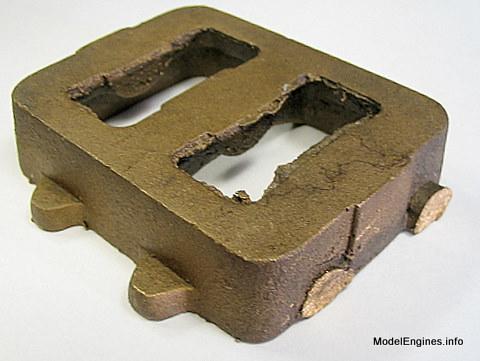
As shown elsewhere on these pages, this was my first step in preparing the castings
Next I roughed out the openings with the side of an endmill to remove flash

Checking the edges to see that they are parallel with the X-axis of the mill prior to scoring the centre line
Scoring the line using a small centre drill in the mill
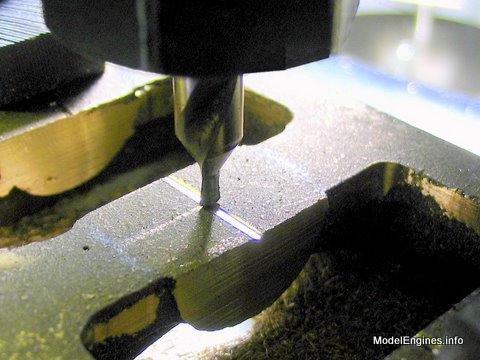
Double-checking with dividers to ensure that the scored line went in the correct place

The position of the crankshaft and the entire upper part of the engine depend on this line for their final location.
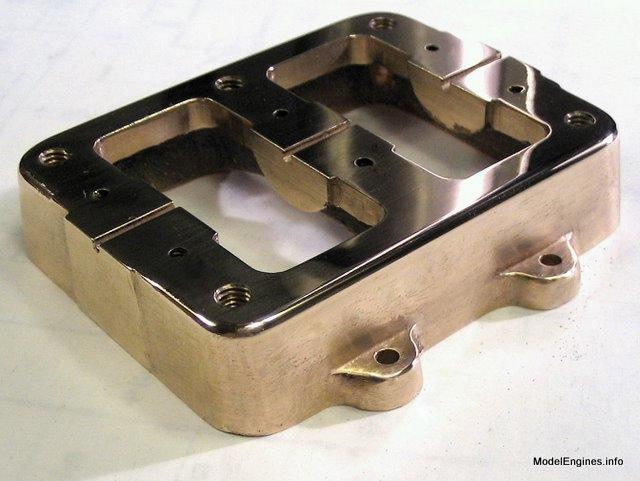
A view of the finished crank recesses
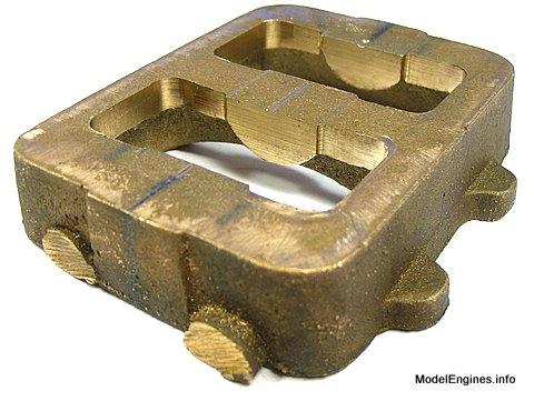
It is a good sturdy casting, offering generous support for the crankshaft main bearings

A view for size reference

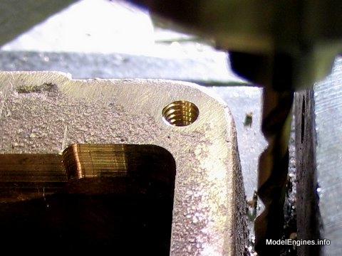
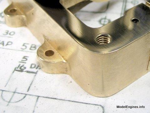
I accurately located the hole for the middle column at the back
(The other four will be referenced to this one)

At first, drilling these holes was a breeze...

But then I realized where the properly-located corner holes are required to be placed!


The final part of this job was taping the holes 5/32" x 40 t.p.i. to match the columns

I used the drill press as a tapping station
After the tap has been threaded in a few turns, it is time to lock the upper nut on the drill press's stop bar to prevent the spring in the quill from trying to rip the tap out of the hole if the quill handle is released.

Then it is a simple matter to use the key in the chuck to release the tap in order that a small tap wrench can be employed to continue tapping by hand with greater sensitivity.

If you are used to looking at North American Unified threads (UNC, UNF etc), the British BA threads will come as a bit of a surprise at first glance.
At a casual glance they will look "worn" to someone not familiar with this type. Don't be fooled - they get a surprising grip for the depth of the threads due to the steeper angle.
Now just a quick pass with a 3/8" endmill over the top surface to prepare for marking and drilling the bearing cap stud holes

Using the Taig mill as a hand tapping station in much the same manner as with the drill press

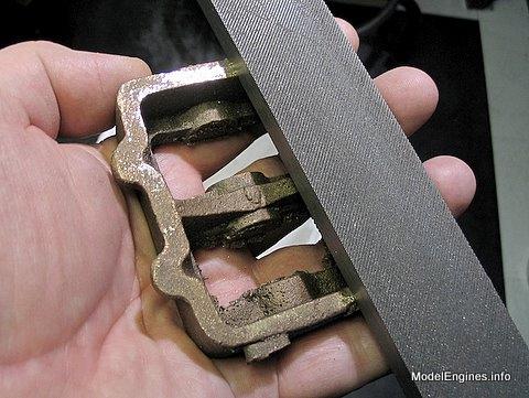
I used a flat file to remove some of the high spots before going to the next step

I wanted to try a sanding drum on a high speed flex shaft (Dremel)

It worked very quickly, but I needed a small rotary stone to get into the corners
(not done yet in this photo)

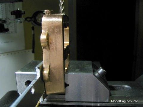
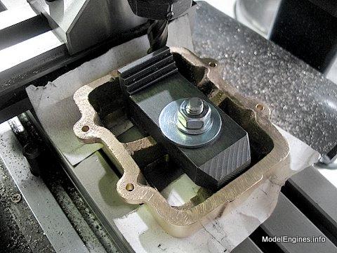
I needed to get the sloping end of the casting parallel to the mill table so I braced it out at the bottom with a brass rod

This view explains the need when milling the ends of the soleplate
Gunmetal is hard to come by in this country - I should have cut this off and sold it!

Getting closer to the final shape

Flattening the bottom prior to bringing the top down to size
..an odd method of clamping but it worked

Now - here's where it starts to get funny...
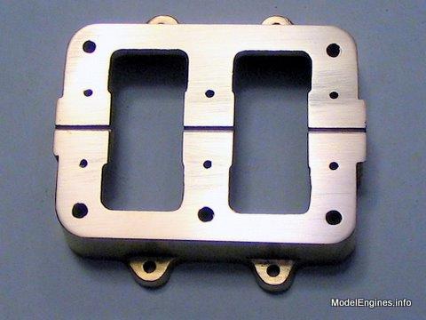
Gunmetal is an excellent bearing metal and very slippery

It produces a shiny surreal surface that is surprisingly "unflat"

Just look at that! - the weirdest thing I have ever seen!

OK, I machined an identical soleplate years before - but that was by hand with a large file
- and that is exactly how this one will be completed

Note the dull flat patches where the file has already hit the high spots
At this point it is ready for polishing
Trimming the perpendicular parts with the side of the endmill

The drawings depict a more rounded curve than this at the top edges
So I have complied with the drawings

Now a quick hand rub with some rouge on a flannel cloth

The soleplate now awaits the carving of the three main bearing journals
If you wish to jump ahead for a look Click Here.
Making the cylinder block supporting columns
I started by turning one end of the 1/4" steel rods to accept a 2BA thread
- then making a centre hole for later finishing the column with tailstock support

Cutting the 2BA thread with a die in the Taig lathe

Preparing the other ends for 4BA threads - not according to the drawings for the Compound

Applying the No.4 BA thread
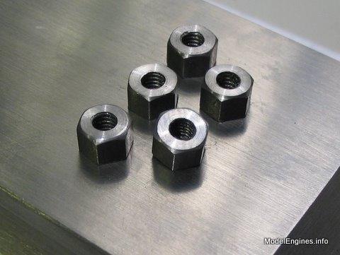
I decided to make new long 4BA nuts - 1/4" across the flats
(which I felt were more appropriate in size than the large flat 2BA nuts provided)

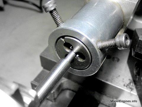
Tapping the hex for the 4BA column ends

The completed set of long pattern nuts
Tightening down on thin stainless steel internal shakeproof washers
(not provided or needed, but I happened to have some)

I really can't see the need of using larger nuts and I think these look more sensible

(it is interesting to note that the company suggests this smaller size in their almost identical Twin Launch engine)
After the exact position of the (crosshead slider/reversing shaft) bracket is ascertained
I may turn the columns down in a "waisted" style

Back to
Compound Launch main page
or
Castings, Materials and Fastenings
Soleplate (this page)
Cylinder Block
Top Covers
Bottom Cylinder Covers
Steam Chests
Crosshead Guides and Bracket
Crankshaft
Eccentrics
Flywheel
Connecting Rods and Crossheads
Main Bearings
Pistons
Fittings: Oil Cups
Fittings: Drain Cocks
Fittings: Exchange Pipe, Flanges and Glands
Stephenson Link Reversing Gear (5 pages)
Completing and Erecting the Compound Launch Engine
or
Return to main website home page
ModelEngines.info
![]()
(c) John R. Bentley 2010.