
John R. Bentley 2010.
Machining the
The raw castings and a nearly finished set
Connecting Rods & Crossheads
- for the Stuart Compound Launch Engine -

Ready to shave off that ugly bit at the bottom

Distance between centers marked - simple job, but important!

Center drilling the hole to take the lathe tailstock center

Of course the crankpin center is "above center"
(to make up for the saw cut when the big end is separated and dressed)

Ready to turn the connecting rod big end's sides and the tapered shaft

Bringing the Taig up to speed (~800 rpm)

The top of the big end will be finished in one of two ways...

A spigot remains after the turning is finished

Spigot removed

Here's one way to do that flat part (before the big end is split)

When making the second rod I switched the order of operations slightly
Here the holes have been drilled and the unit is being sawn in two

Don't get overconfident - cutting slippery gunmetal is somewhat like driving a car on ice
(it doesn't always go where you point it)
Neat ? nope!

...that's what milling machines or files are for ;-)
Protecting the edges with pieces of card in the vise jaws
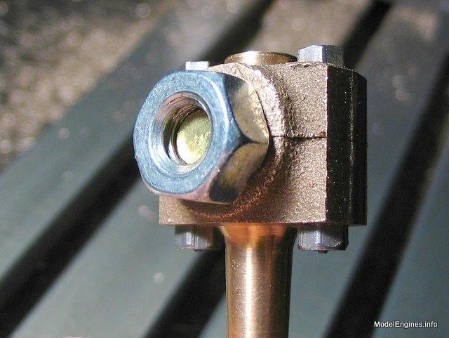
I used a 1/4 inch brass bolt and nut to hold the big end halves together by squeezing their sides

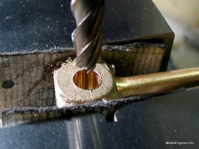
Now the small nuts and bolts can be removed
This allows machining the area where the heads of the 7B bolts normally reside

Hollowing out the slot to accommodate the crosshead

Leaving so little support is not overly safe
You could ruin the part (or your face)
I do not recommend this except with a much smaller diameter cutter than shown

I turned a stub mandrel to guarantee perpendicularity while finishing the sides

Testing out on a piece of 5/16" silver steel - pretty stuff!
(I guess that's called "precision ground drill rod" on our side of the Pond)

I wanted to ensure that the holes at the ends were
parallel in the vertical and horizontal planes

This vise is very accurate.
It has a vertical V-notch which holds the silver steel in a perpendicular position
(hence parallel to the mill's Z-axis)
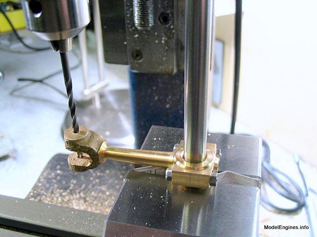
For reasons which will become obvious in the next view
I didn't yet enlarge or thread either of these holes at this end of the rod

I am about to graze the side of the endmill by swiveling the entire rod about a pin
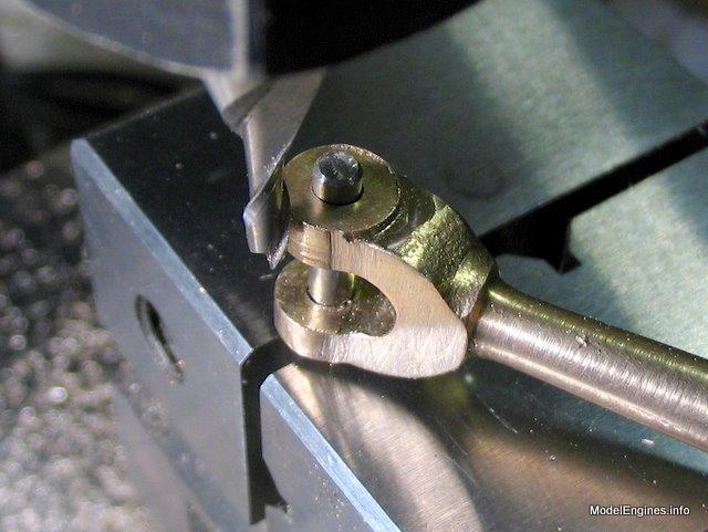
Note that the pin is larger above the top hole to hold the workpiece captive.

This requires great care...
a knucle dragged into the side of a rotating endmill would not be not a pretty sight
Using a radiused endmill to match the flat to the curve

One connecting rod awaiting final finishing by hand
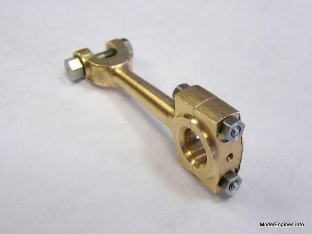
Just checking - before finishing the final end...
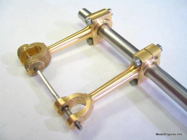
If the two rods won't line up in this fashion, there's going to be trouble!
On to the crossheads: first a skim off all surfaces of the castings

Machining the ferrule to accept the stainless steel piston rod

Knocking off the corner

The hole is tapped 5BA for the piston rod

Reaming the 1/8" hole for the connecting rod stirrup pin
Rods and crossheads - before and after

Compound Launch main page
or
Castings, Materials and Fastenings
Soleplate
Cylinder Block
Top Cylinder Covers
Lower Cylinder Covers
Steam Chests
Crosshead Guides and Bracket
Crankshaft
Eccentrics
Flywheel
Connecting Rods and Crossheads (this page)
Main Bearings
Pistons
Fittings: Oil Cups
Fittings: Drain Cocks
Fittings: Exchange Pipe, Flanges and Glands
Stephenson Link Reversing Gear (5 pages)
Completing and Erecting the Compound Launch Engine
or
Return to main website home page
ModelEngines.info
![]()
(c) John R. Bentley 2010.