
John R. Bentley 2010.
Machining the
This is a two-throw crankshaft having a 90-degree separation with double eccentrics attached at each end
Crankshaft, Eccentrics and Flywheel
- for the Stuart Compound Launch Engine -
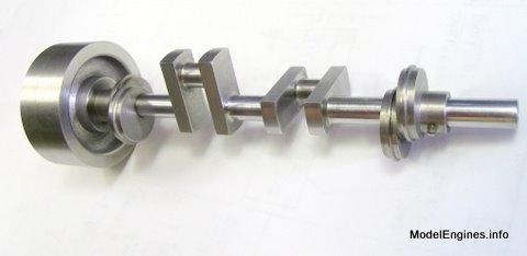
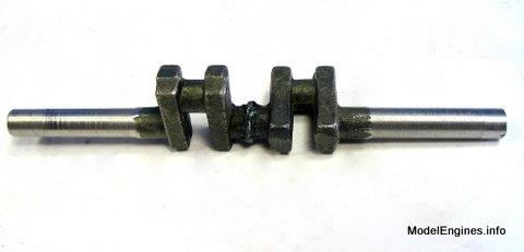
Here is the basic forging as supplied with the castings set
I machined an identical crank for a Stuart Twin Launch 20 years ago.
An unmachined built-up crankshaft was supplied instead of a forged one but the end result looks identical to me.
This one consists of two forgings fused together at 90 degrees at the centre bearing journal

The entire assembly (including the fettled areas) is a uniform colour
I assume that indicates post heat treatment

That should relieve any stresses produced during the fusion of the two parts
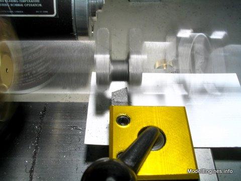
My first step was to place one end in a 3-jaw chuck

Locating an approximate center on the other end by rotating slowly
Once a centre dimple was formed I punched it to mark it better
Centre drilling
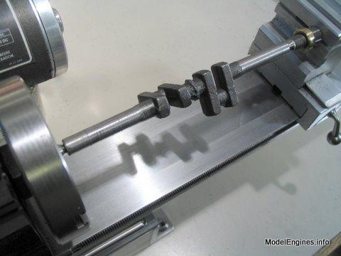
Back in the lathe to rough-turn one of the shaft sections

Flipped end-for-end and supported in the steady rest

Facing the end and turning the last bit of shaft (previously held in the chuck jaws)

Moved back - "close up" in the steady rest arms

Drilling a centre hole in this end

After rough-turning the other main shaft section
Now I'm ready to go to work...
Turning one set of web ends
Face turning the outside of the nearest web

Starting on the centre journal
A view part way through the job

(when turning between two centres it's an easy matter
to take the work out of the lathe for close inspection or photos)
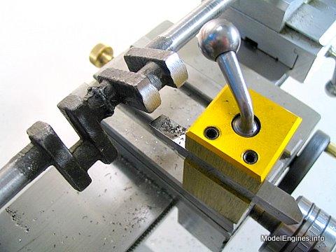
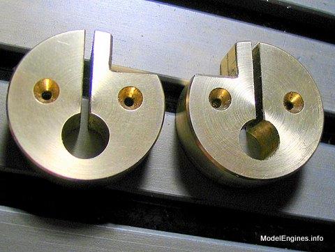
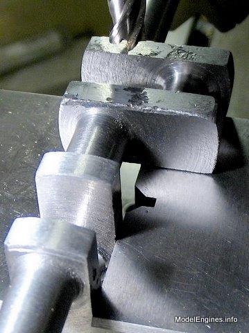
I needed to make turning fixtures in order to machine the crankpins
(and the other ends of the webs)

The two small holes take the lathe centres - each located for turning a separate crankpin
The large hole will clamp on to the end of the straight shaft section
After milling a large notch in the periphery, I cut a long slit from the outside to the shaft hole

Splitting the workpiece to make two
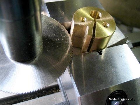
This is Naval Brass from the discarded propeller shaft of an old lobster fishing boat
Now it is just a matter of adding clamping screws at the top
Threading below the slit for the clamping screw

The completed fixtures
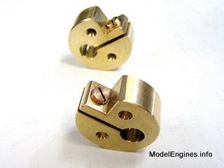
Although this picture was taken after completion, you get the idea!

I put a rubber band in to protect the fixture from the lathe carrier (dog)

Setup off-centre so the crankpin (to the right) is along the lathe axis

Here's the proof of that last statement
(everything is flying around eccentrically but the crankpin is rotating on the lathe axis)
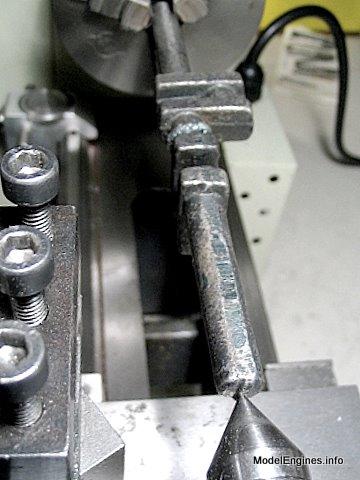
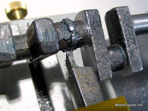
Ready to face the inner sides of the webs

One crankpin finished

Milling the edges of a web in the Taig mill
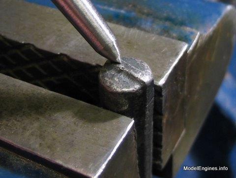
The Lomo stereo microscope assisting in finishing the journals

A closer view

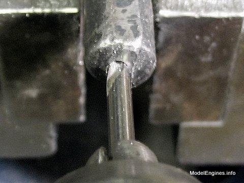
Working on the filleted area with a round nose tool similar to a parting tool.

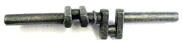
The completed shaft

All this stuff must go together somehow...

Compound Launch main page
or
Castings, Materials and Fastenings
Soleplate
Cylinder Block
Top Cylinder Covers
Lower Cylinder Covers
Steam Chests
Crosshead Guides and Bracket
Crankshaft (this page)
Eccentrics
Flywheel
Connecting Rods and Crossheads
Main Bearings
Pistons
Fittings: Oil Cups
Fittings: Drain Cocks
Fittings: Exchange Pipe, Flanges and Glands
Stephenson Link Reversing Gear (5 pages)
Completing and Erecting the Compound Launch Engine
or
Return to main website home page
ModelEngines.info
![]()
(c) John R. Bentley 2010.