
John R. Bentley 2010.
Machining the
My usual method for rough centering in the chuck is to leave the toolpost loose and turn the cross slide in until the tip touches the workpiece. Then I turn the chuck slowly backwards by hand and note the variation of the gap between the tool and the work. I adjust the jaws accordingly - for a simple job like this one on a rough casting that's as close as you can get.
I prefer to machine this type of valve guide freehand and clean up (carefully) with two small files - a flat file and a round one. (you don't want the file to come in contact with the body of the steam chest or it might just come in contact with your own chest!)
Steam Chests
- for the Stuart Compound Launch Engine -

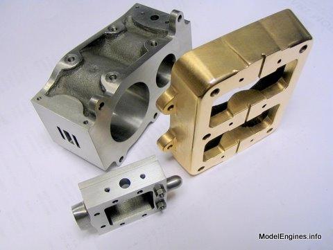
The finished steam chests - the low pressure (L.P.) unit is the larger of the two

The LP end fixed into position
These are the castings for the steam chests as supplied
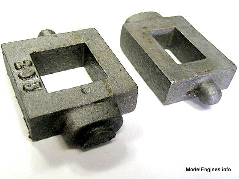
These two units are identical except for the widths, so I will show the work on the LP steam chest with odd shots of the smaller HP unit interspersed among the other photos
Here the casting is clamped into the 3 1/4" Taig chuck


Taking a facing cut across the top

This is the same scene with the lathe stopped part way through the cut

It is best to remove only what is necessary, it's hard to add metal back on...
This is a carbide insert for refinishing car brake drums and disks...I made a little holder to fit the Taig
It has a good radius for freehand jobs like this
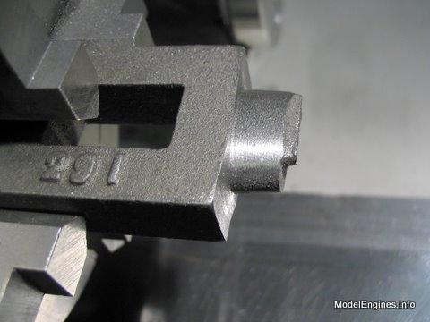
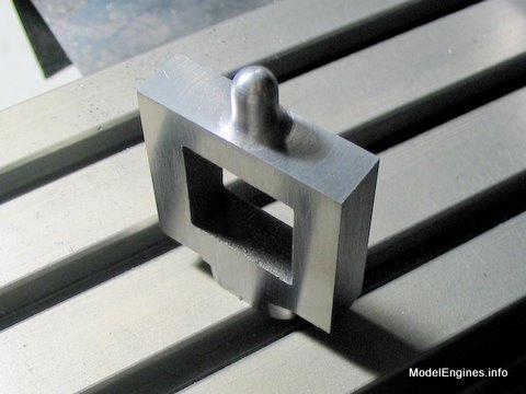
The completed valve rod guide

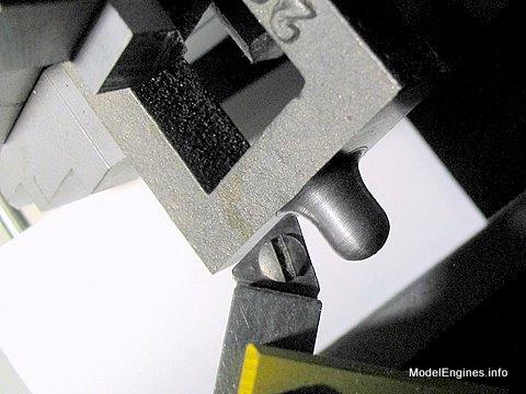
Now to the other end - this will become the packing gland

It is easiest to file this smooth while in the chuck

My lathe will function at almost zero RPM so I was able to revolve it slowly and let the file
undulate as it followed the oval surface of the gland packing box.
All done!
At last - I'll get rid of those numbers!

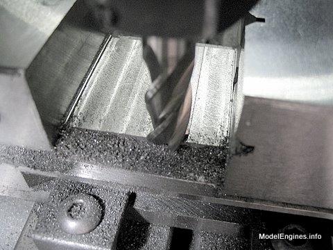
Two 1/4" lathe tool blanks allow clearance for the cutter between the vise jaws
As they say, it is best to get under the crust in the first pass

That looks a little better!
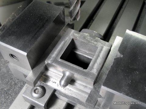
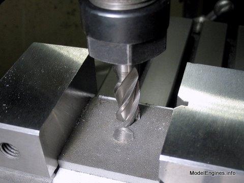
Milling out the 7/8" x 7/8" steam space

I have clamped two strips of steel to protect the body while filing the gland

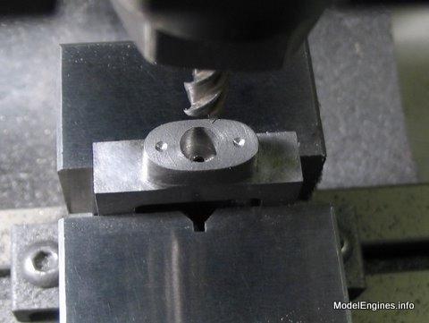
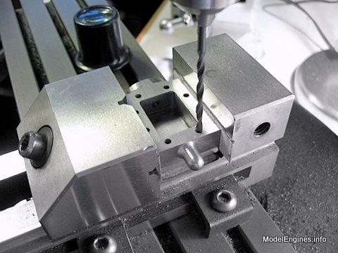
Starting the stud holes and the packing space

Now. I am expected to drill through the gland, through the steam space and deep into the valve guide - that is without coming through the end by mistake. I'm good at mistakes so I am ascertaining that there isn't enough of the drill protruding to make it out the other side!

A proper person would simply turn the the steam chest around on edge in the vise so that the tip of the drill is visible...then they would trust to those little numbers on the mill's Z-axis handwheel.
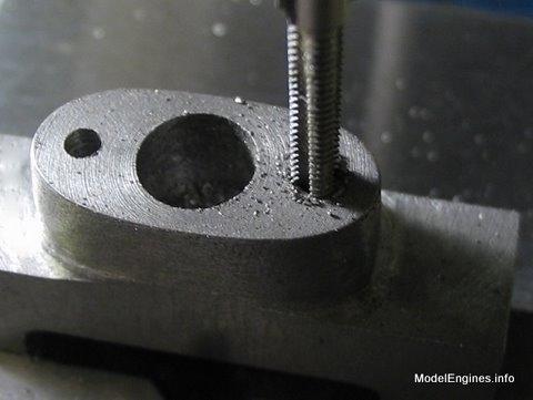
I bored this packing recess in the gland with a 1/4" endmill
Tapping the holes for the 7BA studs which will tighten the gland
Forming the connection for the exchange pipe flange

The exchange pipe conducts the exhaust steam from the High Pressure cylinder to the intake on the Low Pressure steam chest
The eight mounting holes were located with the mill's X and Y axes then started with a center bit

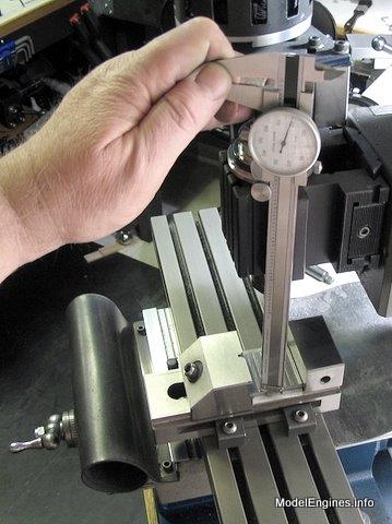
I tried marking out the holes for the studs as a double-check on my setup in the mill
I just slid the caliper's jaw along the edge as a guide and let the other jaw scribe the line in the toolmaker's ink
Just taking a breather while I contemplate the covers

When I get back to the cylinder block it will be time to tap the eight holes on each end

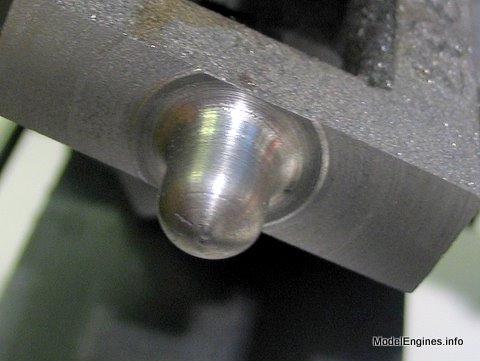
The covers have a spigot on the back so they can be faced in the lathe

Judging from this cut, the spigot is not exactly square with the cover
(that's OK there is plenty of extra thickness of metal)

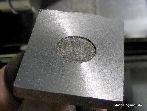
Completely under the "crust"

Here is the smaller cover from the HP valve chest

It turned this cover at the same time
It will be drawn over fine silicon carbide paper to remove turning marks
Milling the edges clean while the spigot is still attached
(but not all the way - I am leaving a little extra for endmill clearance in the vise)
Sawing it off

It's gone!

Making a pass
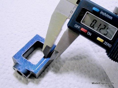
This is a good time to use the depth gauge included on the end of every dial caliper

The plans call for 0.125" thickness
Note the ridges left at the sides to give clearance for the cutter
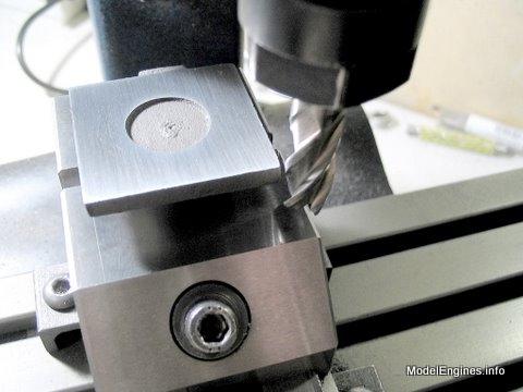
Now I simply hold it vertically in the vise and mill the edges to bring the cover to specified dimension, thus removing the ridges left in the last step.

I will probably mill off that blemish in the centre while trying to retain the "cast look"

The holes have been drilled through the cover using the body as a drilling guide
A view of some nearly-completed parts
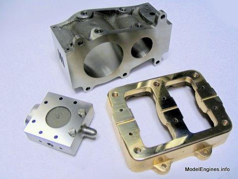
A stark contrast is evident between the raw casting (bottom) and the finished valve chest

This much was accomplished over a span of 26 days
Compound Launch main page
or
Castings, Materials and Fastenings
Soleplate
Cylinder Block
Top Cylinder Covers
Lower Cylinder Covers
Steam Chests (this page)
Crosshead Guides and Bracket
Crankshaft
Eccentrics
Flywheel
Connecting Rods and Crossheads
Main Bearings
Pistons
Fittings: Oil Cups
Fittings: Drain Cocks
Fittings: Exchange Pipe, Flanges and Glands
Stephenson Link Reversing Gear (5 pages)
Completing and Erecting the Compound Launch Engine
or
Return to main website home page
ModelEngines.info
![]()
(c) John R. Bentley 2010.